Solder a Custom PCB
This Saturday, I soldered my custom PCB for the KiCad workshop, where we make a simple board that blinks two LEDs alternately with a NE555 timer chip. Here is the schematic:
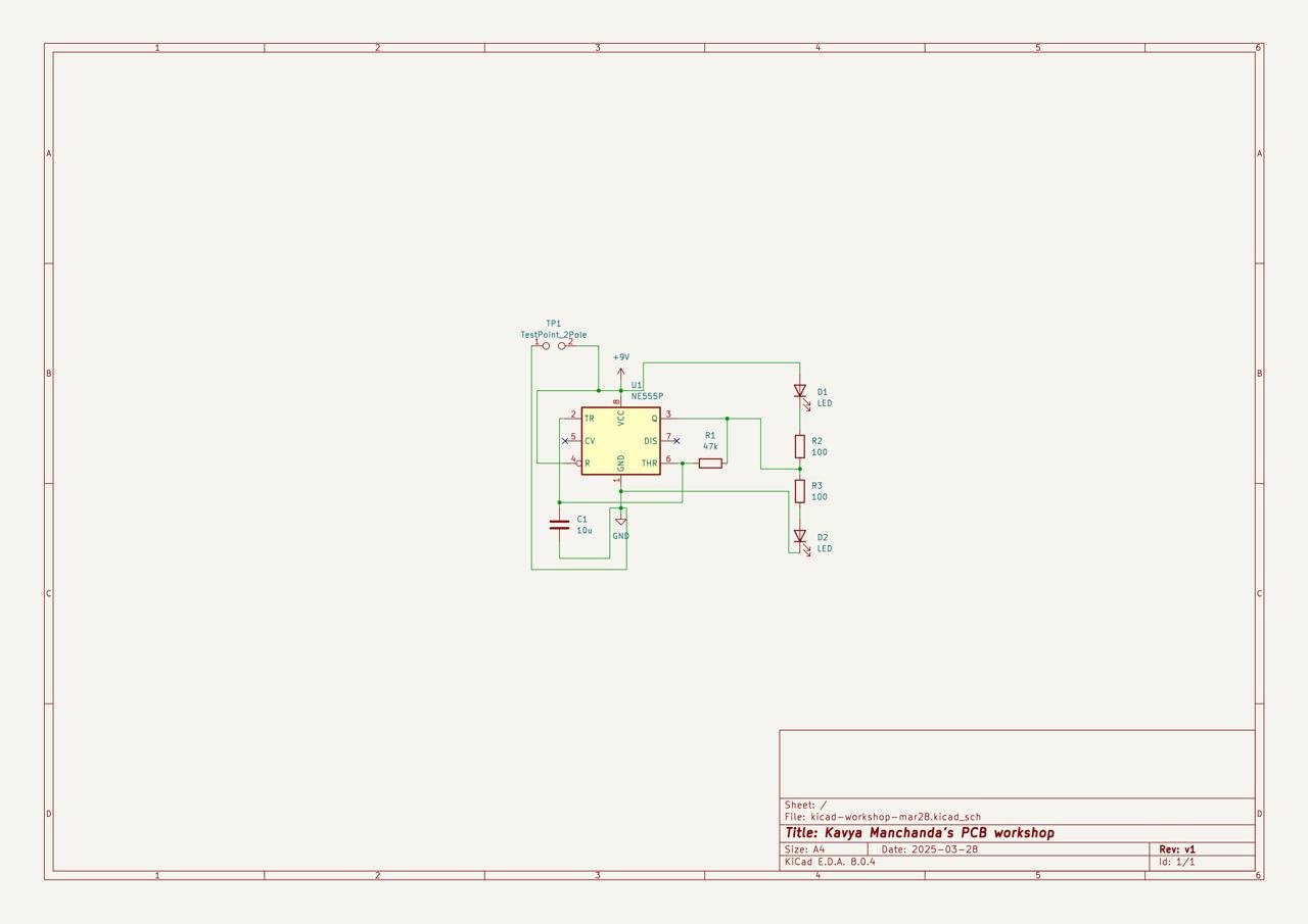
Schematic of a PCB Board which blinks two LEDs alternately
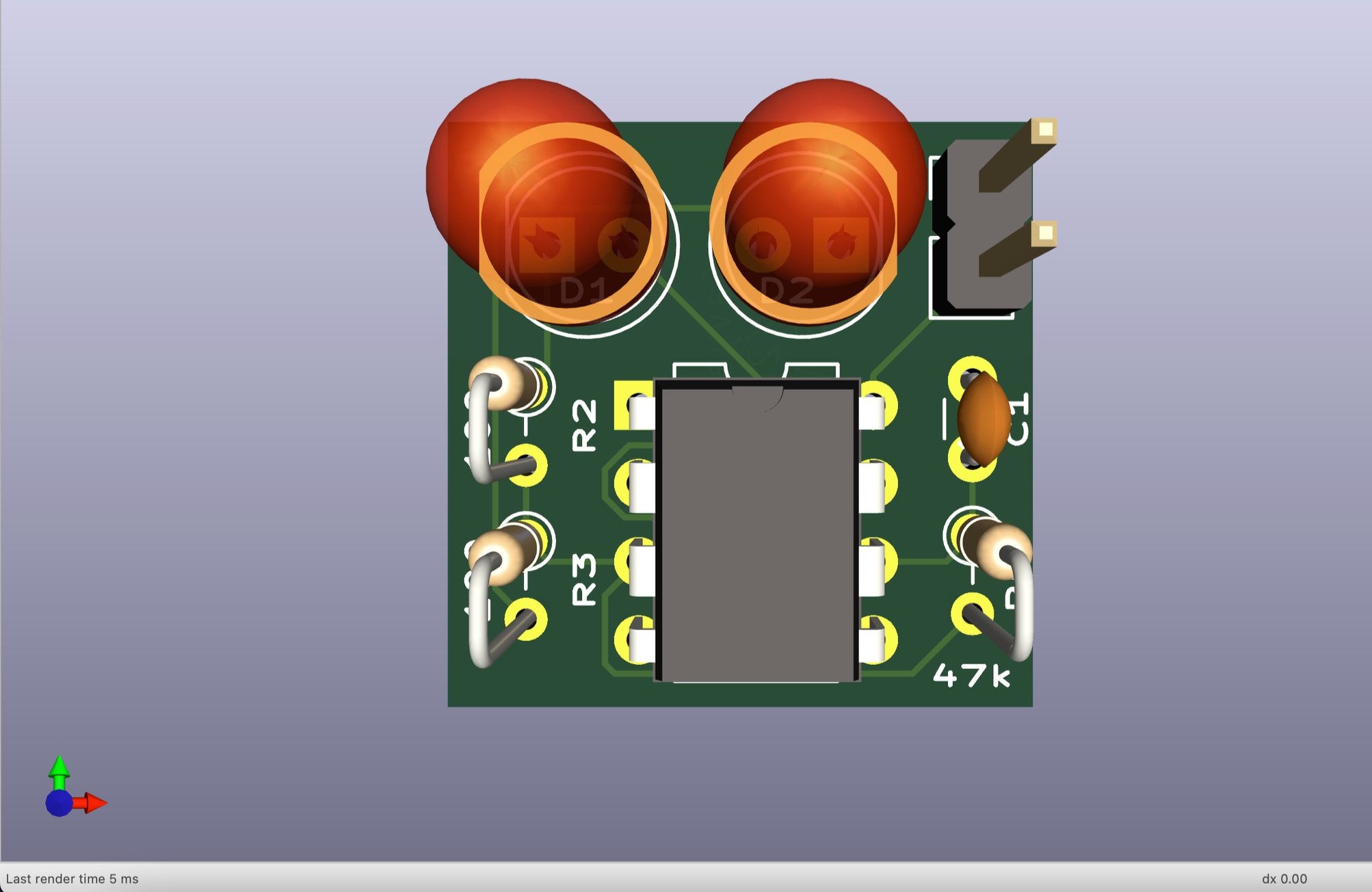
Here is the PCB Board Front and Back:
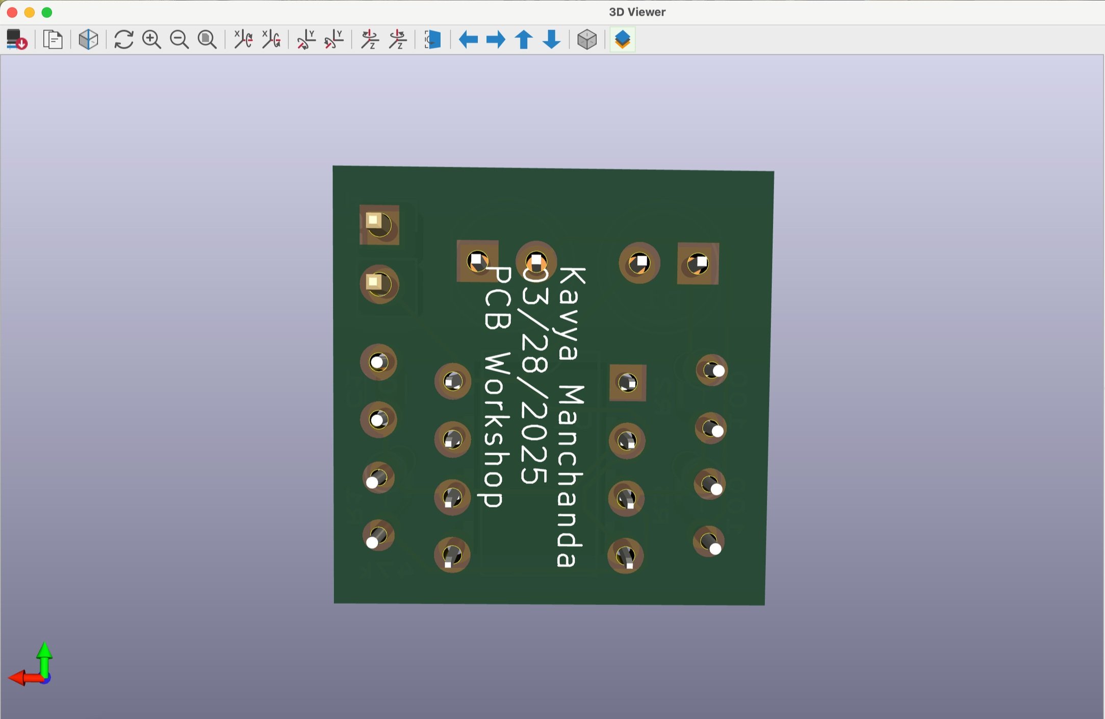

The area of my PCB is 0.75 in * 0.75 in or 19mm * 19mm, which is 0.559551 in² or 361 mm². I checked the cost on manufacturers OSHPark and JLCPCB - being 2.75 USD on OSHPark and about 5 USD on JLCPCB, with Lead-Free HASL finishing (more coming on this soon!).
After two weeks, the PCB finally arrived. I quickly realized I had chosen a much smaller footprint for the 2-pole test point—1 mm pitch instead of the standard 2.5 mm. If you're new to soldering, the tight spacing can be tricky, but I’m sure you’ve got this! I decided to use a 22 AWG 7/30 Stranded wire for my test points. Only 2 strands were inserted into the holes, which made it thinner to ~28 AWG.
The good thing about JLCPCB is that we get 5 copies of our PCB. So, you have the flexibility of making mistakes. Those who participated in the workshop have their PCBs arrived and ready to be soldered. You too, can get your dream circuit made in real life at M5!